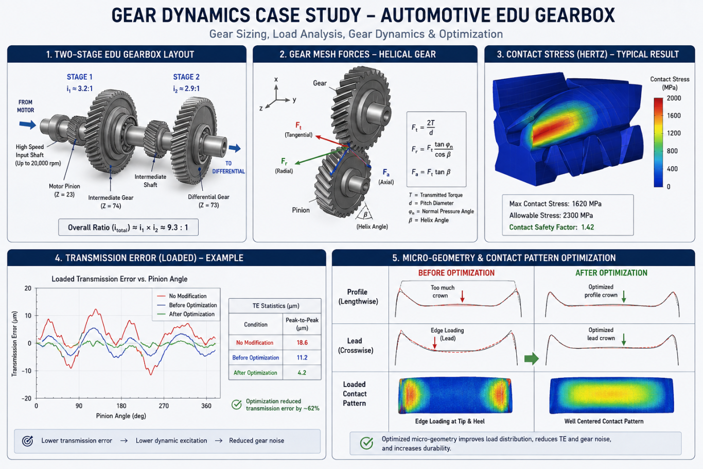
Gear Dynamics
High-Speed Geartrain Design for an Electric Drive Unit
Project Overview
The objective of this project was to develop and validate a compact, high-efficiency geartrain for an automotive Electric Drive Unit (EDU).
Unlike conventional ICE transmissions, an EDU gearbox operates at significantly higher input speeds while transmitting high torque through a compact package. The combination of high rotational speed, aggressive packaging targets, low-loss requirements, and stringent vehicle NVH expectations makes gear sizing and gear dynamics critical to the overall EDU design.
Our engineering study focused on developing a gearset that could satisfy:
- Required overall transmission ratio
- Peak and continuous motor torque
- High-speed operation
- Gear tooth bending strength
- Pitting and contact fatigue resistance
- Low transmission error
- Reduced gear whine
- High mechanical efficiency
- Bearing and shaft load limitations
- Packaging constraints
- Manufacturing feasibility
- Target vehicle durability life
- Engineering Challenge
The EDU architecture required a large speed reduction between the electric motor and the differential while maintaining a compact transmission envelope.
A representative operating requirement was considered:
Motor maximum speed: ~16,000–20,000 rpm
Peak motor torque: ~300–400 Nm
Continuous motor torque: ~150–250 Nm
Required total reduction ratio: ~8.5:1–10.5:1
Gearbox architecture: Two-stage parallel-axis reduction
Target efficiency: >97% across the primary operating region
The primary challenge was not simply obtaining the required ratio.
The gearset also had to withstand peak vehicle loads, repeated torque reversals, regenerative braking loads and high-cycle fatigue while keeping gear mesh excitation sufficiently low for an EV application.
1. Transmission Architecture Development
A two-stage reduction architecture was selected to distribute the overall transmission ratio across multiple gear meshes.
A representative ratio split was:
Stage 1
Motor Pinion → Intermediate Gear
Ratio ≈ 3.0–3.5
Stage 2
Intermediate Pinion → Differential Gear
Ratio ≈ 2.7–3.2
Resulting in an overall transmission ratio of approximately:
Overall Ratio ≈ 9:1–10:1
The ratio distribution was optimized rather than simply divided equally between the two stages.
The evaluation considered:
- Gear pitch diameters
- Tooth numbers
- Hunting tooth combinations
- Center distances
- Pinion tooth bending strength
- Contact stresses
- Intermediate shaft torque
- Bearing reaction loads
- Gear mesh frequencies
- Available housing envelope
This architecture-level optimization helped prevent one gear mesh from becoming the dominant durability or NVH constraint.
2. Gear Sizing
Initial macro-geometry was developed from the transmitted torque, ratio requirement, target center distances and material capability.
Key gear parameters evaluated included:
- Normal module
- Number of teeth
- Helix angle
- Normal pressure angle
- Face width
- Addendum modification
- Tip diameter
- Root diameter
- Reference diameter
- Center distance
For a helical gear pair, the transmitted tangential force was determined from:
Ft = 2T / d
where:
Ft = Tangential gear force
T = Applied torque
d = Gear pitch diameter
The radial and axial components generated by the helical gear mesh were then determined and transferred into the shaft and bearing models.
Particular attention was given to the motor pinion because it simultaneously experienced:
- Highest rotational speed
- Relatively small pitch diameter
- High tooth loading
- High mesh frequency
- Increased sensitivity to manufacturing errors
- Significant contribution to gearbox whine
Several module, tooth-count and face-width combinations were compared before the final gear proportions were selected.
3. Load Spectrum Definition
Designing an automotive gearset only for peak torque can produce misleading results.
The gearbox therefore had to be evaluated against a representative operating duty cycle.
The load spectrum included:
- Vehicle launch
- Maximum acceleration
- Continuous cruising
- Hill climbing
- Maximum vehicle speed
- Regenerative braking
- Torque reversal events
- Traction-control events
- Overspeed conditions
- Motor torque and speed histories were converted into gear mesh loads for each transmission stage.
- Damage accumulation was then assessed across the duty cycle rather than using a single static operating point.
This approach allowed the gear geometry to be optimized simultaneously for peak strength and fatigue life.
4. Gear Tooth Bending Analysis
Gear root bending stress was evaluated to determine the risk of tooth-root fatigue.
The analysis considered factors including:
- Applied tangential load
- Tooth geometry
- Face width
- Load distribution
- Dynamic effects
- Manufacturing quality
- Material fatigue strength
- Temperature
- Reliability requirements
Calculations were performed using recognized gear rating methodologies such as ISO 6336 / AGMA-based approaches, depending on project requirements.
The highest bending stress typically occurred on the smaller pinions because fewer teeth and smaller root sections must carry the transmitted load.
Design iterations included changes to:
- Module
- Root fillet geometry
- Profile shift
- Face width
- Tooth number
- Material specification
until the required bending safety factors were achieved.
5. Contact Stress & Pitting Resistance
In addition to tooth-root fatigue, the gear flanks were evaluated for Hertzian contact stress.
High contact stresses can result in:
- Micropitting
- Macropitting
- Surface distress
- Progressive gear noise
Reduced transmission durability
The contact analysis accounted for:
- Gear geometry
- Material elastic properties
- Surface hardness
- Tooth flank curvature
- Face load distribution
- Lubrication conditions
- Surface finish
- Operating temperature
The design was iterated to achieve an acceptable contact safety factor over the required vehicle lifetime.
Surface durability was particularly important for the high-speed first-stage gear mesh.
6. Gear Mesh & Transmission Error Analysis
For an EDU gearbox, meeting static strength requirements is only part of the design challenge.
Electric motors generate relatively low background noise compared with internal combustion engines. As a result, gear mesh excitation can become a dominant vehicle noise source.
The gear pairs were therefore evaluated for Loaded Transmission Error (LTE).
Transmission error represents the deviation from ideal angular motion transfer between mating gears.
Variations in transmission error generate excitation forces at the gear mesh frequency and its harmonics.
Key contributors include:
- Tooth deflection
- Gear body deformation
- Profile errors
- Lead errors
- Shaft deflection
- Bearing displacement
- Housing deformation
The objective of the gear dynamics study was therefore to reduce both:
- Peak-to-peak transmission error
- Sensitivity of transmission error across the operating torque range.
8. Micro-Geometry Optimization
Gear micro-geometry modifications were introduced to improve load distribution and reduce transmission error.
The study considered modifications such as:
- Profile crowning
- Lead crowning
- Tip relief
- Root relief
- End relief
- Helix slope correction
Micro-geometry optimization was performed across multiple torque levels.
This is important because a correction optimized only for peak torque may generate unacceptable transmission error during low- or medium-load vehicle operation.
The final geometry targeted a compromise between:
Durability + NVH + Manufacturing Robustness
rather than optimizing a single operating point.
8. Shaft & Bearing Deflection
Gear tooth loading cannot be evaluated independently from the supporting structure.
Gear mesh forces were transferred into a shaft and bearing model to calculate:
- Shaft bending
- Shaft torsion
- Bearing reaction forces
- Bearing displacement
- Gear misalignment
Even small angular misalignment across the gear face can significantly change the contact pattern.
Without compensation, this can lead to edge loading and localized contact stress.
The predicted misalignment was therefore incorporated into the gear contact analysis and micro-geometry design.
9. Bearing Load Analysis
Helical gears generate axial forces in addition to radial and tangential forces.
Bearing reactions were evaluated for:
- Maximum motor torque
- Regeneration
- Reverse torque
- Maximum vehicle speed
- Combined radial and axial loading
- Bearing selection considered:
- Dynamic load rating
- Static load rating
- L10 life
- Speed capability
- Lubrication
- Preload
- Thermal expansion
The helix direction of the two gear stages was also reviewed to manage axial loads within the intermediate shaft assembly.
10. Gear Dynamics & Mesh Frequency Evaluation
For each gear pair, the primary gear mesh frequency was calculated from:
Gear Mesh Frequency = Rotational Frequency × Number of Teeth
For example, a 23-tooth motor pinion operating at 18,000 rpm produces:
Motor rotational frequency:
18,000 / 60 = 300 Hz
Gear mesh frequency:
300 × 23 = 6,900 Hz
This high-frequency excitation can fall within a sensitive audible range.
The gearbox dynamic study therefore reviewed:
- Gear mesh frequency
- Harmonics
- Shaft natural frequencies
- Gear modes
- Housing modes
- Bearing support stiffness
Potential resonance conditions were identified by comparing excitation orders against predicted system natural frequencies.
11. Efficiency & Power-Loss Assessment
Mechanical efficiency is especially important in an electric powertrain because gearbox losses directly affect vehicle range.
Loss mechanisms considered included:
- Gear mesh friction
- Bearing losses
- Seal losses
- Lubricant churning
- Windage
Gear sliding velocity and contact conditions were evaluated across the motor speed range.
Engineering Outcome
The final EDU gearbox design achieved a balanced solution between performance, durability and NVH.
Key outcomes included:
- Required overall EDU reduction ratio achieved
- Gear tooth bending safety factors within target limits
- Contact fatigue performance suitable for the target vehicle life
- Reduced peak contact stress through improved load distribution
- Optimized profile and lead modifications
- Reduced loaded transmission error
- Improved contact pattern across the gear face
- Controlled bearing and shaft loads
- High predicted mechanical efficiency
- Gear geometry compatible with automotive manufacturing processes
The study demonstrates that successful EDU gearbox development requires much more than selecting a module and calculating gear ratio.
Gear macro-geometry, structural deflection, tooth contact, micro-geometry, lubrication and drivetrain dynamics must be developed as a coupled system.
Key Engineering Capabilities Demonstrated
Gear Design
- Gear ratio definition
Gear tooth number selection
Module optimization
Helix angle selection
Face-width optimization
Profile-shift optimization
Center-distance definition
Gear Durability
- Tooth-root bending analysis
Contact stress analysis
Pitting assessment
Micropitting evaluation
Duty-cycle fatigue assessment
Gear safety-factor calculation
Gear Dynamics
- Loaded transmission error
Gear mesh excitation
Gear mesh frequency analysis
Order analysis
Gear whine investigation
Resonance assessment
Tooth Contact Analysis
- Contact pattern prediction
Load distribution
Edge-loading assessment
Misalignment sensitivity
Gear Micro-Geometry
- Profile relief
Lead crowning
Tip relief
End relief
Helix correction
Drivetrain Analysis
- Shaft deflection
Bearing loads
Bearing life
Gear misalignment
Torque-path analysis
EDU Performance
- Gearbox efficiency
Power-loss evaluation
High-speed operation
Lubrication assessment
Thermal considerations
A successful design must simultaneously address:
Strength | Durability | Efficiency | NVH | Packaging | Manufacturing
Integrating gear sizing, structural analysis and gear dynamics early in the development process allows potential durability and NVH problems to be identified before prototype hardware is manufactured.
This can significantly reduce physical development iterations and support a faster, more robust EDU design process.